
Thank you for visiting the RAMCHECK web
site, the original portable memory tester.
RAMCHECK LX APPLICATION NOTE INN-8686-APN3
INN-8686-APN3
--Created: 9-22-08
--Updated: 11-25-16
There are a variety of Automatic Module Device Handlers that automate the process of testing a large number of memory modules. This document illustrates how such an Automatic Handler can be interfaced with the RAMCHECK LX. We offer the RAMCHECK LX Handler Interface package (p/n INN-8686-HI) which includes the control cable and special activation code. While originally developed to work with the INNOVENTIONS brand of SIMM handlers, our customers may use the following information to interface the RAMCHECK LX to their current handler.
The Automatic Handler places a module into the test site so that a tester like the RAMCHECK LX is connected to the module contacts and applies the memory test. If the test is successful, the tested module is automatically moved to a PASS bin, while if the test fails, the module is moved to the FAIL bin. Generally, there are two types of handlers in the market:
Fig. 1 provides an overview of the RAMCHECK LX interface to the most common Automatic Handler. In this example, the handler has an internal test site which comprises a set of contactors that attach automatically to the module once it is mobilized into the test site. The test site's contactor should be connected to the RAMCHECK LX's test socket.
IMPORTANT NOTE: Customers interfacing RAMCHECK LX to their existing Handler must resolve the Test Site Interface issue in accordance with their specific Handler. The Test Site Interface is not included with the INN-8686-HI RAMCHECK LX Handler interface. Make sure that the Test Site Interface you build for your Handler insures short connections and is well designed to reduce stray capacitance and other unwanted loading that will reduce the frequency limit of the test.
The RAMCHECK LX must be placed in a mechanically secured position very near to the handler, typically by a shelf or a strong set of brackets.
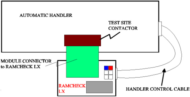
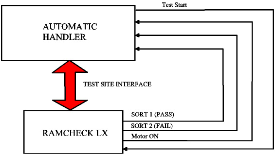
The Handler control cable that is included in the INN-8686-HI provides command signals between the RAMCHECK LX and the Handler. These include the test start signal (from the Handler to RAMCHECK) and the test results Sort1 (GO - PASS), Sort2 (NO GO - FAIL), and the Motor Control signals (from RAMCHECK LX to the Handler). A special activation code is installed onto the RAMCHECK LX to activate its Handler's Control Interface.
Fig. 2 illustrates the block diagram of RAMCHECK LX interface to the Handler.
As mentioned above, when interfacing RAMCHECK to your special Handler, you must provide the test site connector yourself.
The INN-8686-HI RAMCHECK LX Handler Interface kit includes two cables to connect the RAMCHECK 16-pin expansion slot and a typical 15-pin D-SUB Handler's control connector. Once you verify the wiring diagram of your Handler (using the following information), you should connect the ends of the 16-pin and 15-pin cables of the INN-8668-HPAL kit to create your "customized" Handler control cable.
Many handlers use a 15-pin D-SUB connect to control the Handler. Typically, the INNOVENTIONS' older Handler INN-818 and INN-828 use a 15-pin D-SUB control connector with the following pin-out:
| Pin Number | Function |
| 1 | 5V DC |
| 3 | Sort 2 (Fail) |
| 4 | Sort 1 (Pass) |
| 5 | Test Start |
| 6 | Motor Control |
| 9 | Ground |
Pins 2,7, 8, and 10-15 are not used. You must verify that your Handler uses similar connectors, and identify the specific connections.
The RAMCHECK LX Handler connector is a 16-pin IDC connector placed on the right side of the unit, below the USB connector. The pin-out of this connector is as follows:
| Pin | Function | Pin | Function |
| 1 | NC | 9 | GND |
| 2 | NC | 10 | NC |
| 3 | SORT 2 (FAIL) | 11 | NC |
| 4 | SORT 1 (PASS) | 12 | AUX_IN |
| 5 | START | 13 | CODE1 |
| 6 | Motor Control | 14 | CODE2 |
| 7 | NC | 15 | CODE3 |
| 8 | NC | 16 | 5V DC |
The 16-pin IDC connectors are arranged in two rows of 8 pins, and the standard numbering goes as follows: 1-rightmost pin on top row, 2-rightmost pin on bottom row, 3- second rightmost pin on top row, 4-second rightmost pin on bottom row, and so on. Pins marked NC are not connected internally. The extra three outputs CODE1,2,3 and the input AUX_IN are not part of the Handler interface. They are used by the RAMCHECK LX optional printer interface and may be customized for use by specific Handlers. All of the control signals are TTL compatible and are interfaced within the RAMCHECK LX by a Texas Instrument SN74LVT244B which is powered by 3.3V with 5V tolerance.
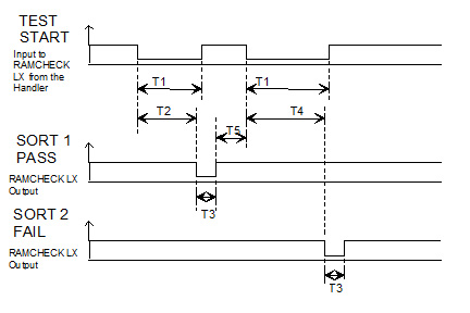
The control interface is quite simple and is outlined in Fig. 3. The timing requirements are as follows:
T1- TEST START SIGNAL - RAMCHECK LX starts the test upon transition to low. Signal remains low during the test, until the tested module leaves the test site.
T2- TEST BY RAMCHECK LX, with good module. The successful test termination point (after Basic Test or Extensive Test) can be configured by the test-flow setup. For example, you can setup the test flow to skip Basic Test so that the Handler PASS/FAIL determination occurs after Extensive Test. Alternatively, very fast partial test can be made using the Quick Basic Test feature.
T3- SORT 1 (Pass) or SORT 2 (Fail) - Currently 100mS for Pass signal, 500mS for Fail signal. Can be customized to customer's specifications. Please note that RAMCHECK LX generates the SORT1 or SORT2 after the test so that the Handler resets the TEST START SIGNAL back to a high level.
T4- TEST BY RAMCHECK LX, WITH BAD UUT, >=T2 DEPENDING ON TEST ALGORITHM.
T5- Delay between the end of one test result and the start of the next test. MINIMUM is typically 300 mS, which is much shorter than the actual time it takes to feed a new module to the test site.
For more information, please call us at 1-281-879-6226 M-F 9:00-5:00 US Central Time, or send your e-mail to support@innoventions.com, or fax your message to 1-281-879-6415. Please remember to include your phone and e-mail.