
RAMCHECK LX DDR3/2
RAMCHECK LX DDR3
RAMCHECK LX DDR2
RAMCHECK LX DDR1
RAMCHECK LX Base Tester
240-pin DDR3 DIMM
204-pin DDR3 SO-DIMM adapter
204-pin DDR3 SO-DIMM converter
240-pin DDR2 DIMM
200-pin DDR2 SO-DIMM adapter
200-pin DDR2 SO-DIMM converter
184-pin DDR Pro
200-pin DDR SO-DIMM converter
100-pin DDR SODIMM
66-pin DDR Chip
DDR2 MiniDIMM
168-pin SDRAM
144-pin SDRAM SO-DIMM
100-pin SDRAM SO-DIMM
SDRAM Chip
200-pin Sun DIMM
50-pin EDO TSOP
EDO/FPM SOJ
72-pin SODIMM
30/72-pin SIMM
Which System Is For Me?
Why Buy From Us?
Why Test Memory?
Int'l Distributors
How to Purchase
Tech Support
Service & Upgrades
Manuals
Software Downloads
FAQ
Site Map
Home
Contact us at
(281) 879-6226
sales@innoventions.com
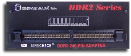
RAMCHECK DDR2 240-PIN ADAPTER
|
Introducing the RAMCHECK DDR2 Adapter (p/n INN-8668-15), our second
generation 800MHz advanced memory test adapter for RAMCHECK or RAMCHECK LX The RAMCHECK DDR2 adapter
supports testing of 240-pin PC2-3200, PC2-4300, PC2-5300/PC2-5400 and PC2-6400
DDR2 memory, including unbuffered and registered modules (ECC and non-ECC) that
comply with JEDEC standards. |
 |
 No
special setup is required. As with all of our products, the adapter is
extraordinarily simple to use. Insert the adapter, turn the RAMCHECK/RAMCHECK
LX tester on, place a module into the test socket, then press the start button.
No
special setup is required. As with all of our products, the adapter is
extraordinarily simple to use. Insert the adapter, turn the RAMCHECK/RAMCHECK
LX tester on, place a module into the test socket, then press the start button.
We have incorporated state-of-the-art technology into the design of the new RAMCHECK DDR2 Adapter. The following pictures provide you with a look "under the hood."
DDR2 Advanced Technology 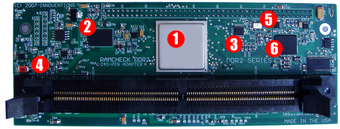 |
||||||||||||||
|
The new RAMCHECK DDR2 adapter includes many new features which are relevant to the differences between the DDR2 technology and the older DDR technology. It also includes many of the advanced features first introduced with our DDR Pro. Please see the screen shots below.
Introducing
the RAMCHECK DDR2
|
||||||||||||||||||||||||||||||||||||||||||||||||||||||||||
As with all of our RAMCHECK testers, each module's size, structure, and type are automatically detected, without the need for user's setup. The test flow follows our standard Basic Test, Extensive Test, and Auto-Loop process. The RAMCHECK DDR2 adapter is very simple to operate, with little training or setup required.
When ordering, please reference RAMCHECK DDR2 Adapter part number: INN-8668-15. Please note that older RAMCHECK base testers may require a hardware upgrade in order to use the DDR2 adapter. Please refer to this RAMCHECK upgrade page for more details.
Please click here for the DDR2 Adapter manual addendum.