
Thank you for visiting the RAMCHECK web
site, the original portable memory tester.
RAMCHECK LX APPLICATION NOTE INN-8686-APN4
INN-8686-APN4
--Created: 1-31-13
--Updated: 10-14-16
This application note discloses partial information regarding the RAMCHECK LX USB Interface Protocol. This information is intended for advanced users wishing to implement their own computer interface program. The information may also be used for USB interface troubleshooting.
| IMPORTANT LICENSING NOTE |
| The RAMCHECK LX USB Protocol is the proprietary information of INNOVENTIONS Inc., covered by copyright, patent pending, and trade secret protections. Users are hereby granted the use of the enclosed information only in conjunction with INNOVENTIONS' RAMCHECK LX units. INNOVENTIONS Inc. reserves the right to incorporate any change in said protocol without prior notice. |
The RAMCHECK LX uses a USB interface chip built within its internal processor board which is similar to the popular chips manufactured by FTDI Chip. The RAMCHECK LX PC Communications package uses USB Drivers provided by FTDI.
The RAMCHECK LX PC Communications package provides the following main functions:
The RAMCHECK LX PC Communications package is the best starting point for custom developers to learn how to access the RAMCHECK LX via USB. The PC Communications FIND button detects the presence of the RAMCHECK LX. Setup and SPD data files are read from the tester and sent to the tester as a string of characters. Test Log data is sent dynamically from the tester to the PC with special strings as shown below. Similarly, other commands are employed in the communication protocols.
It is crucial to understand that our interface protocol is modeled as two relatively independent peers. This creates a loose, non time-critical communication between RAMCHECK LX and the PC in order to retain RAMCHECK full independence. As a result, one can turn off the PC while the RAMCHECK LX is still performing a complex memory test. The only result of communication being lost will be a gap in the PC Test Log data. And of course, the tester operates the same with and without the PC interface. As a result, some non-critical info commands are sent from and to the tester without the need of acknowledgment. You will find this feature to be very useful in simplifying your own interface program!
The main design constraint of the USB Protocol was to avoid any task overhead on the RAMCHECK LX main memory test routines, in order to retain the stand-alone advantage of our architecture. Therefore it is implemented with short communication streams (typically 4 to 6 bytes) from the PC to RAMCHECK LX. All lengthy communications of test results from RAMCHECK LX to the PC are made only between memory test subroutines.
The PC Communications program for the RAMCHECK LX includes a USB diagnostics tool, which allows you to view some of the serial streams between the PC and the tester. Specialized streams, like bitmaps, setup files and other proprietary data structures are intercepted and interpreted by other components of the PC Communications and our not channeled to the diagnostics tool. For example, if you open the USB Diagnostics and press the RAMCHECK LX Setup button, the RAMCHECK LX Setup viewer will appear, already interpreting the setup data in the proper graphics representation. When you switch back to USB Diagnostics, you will not see the setup data which was already interpreted and used. Therefore, we recommend advanced developers use a PC USB viewer/debugger outside the PC Communication package to capture all the data streams.
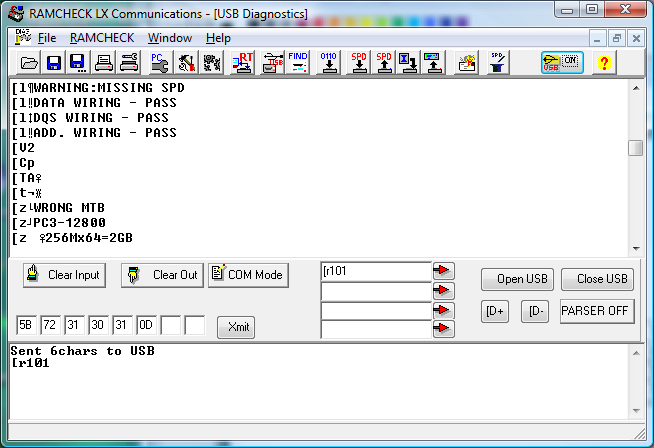
The USB Communications Diagnostics can be activated from the RAMCHECK menu, or using the associated speed button marked USB. The view is split into a top Input window showing the input strings and a bottom Output window for displaying commands that are sent to the tester. Please click the top Input window with your mouse before typing commands to be sent to the RAMCHECK LX. The typed command will appear in the bottom Output window.
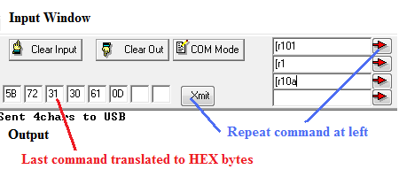
Repeated short commands may be entered in the center text edits and sent with the associated red arrow buttons. Each command sent this way is automatically translated to its ASCII equivalent in hex notation and listed byte by byte left of the Xmit button. This is useful if you need to create short commands that combine characters and hex values as explained below. The COM Mode button allow users to add comments in the Input window. The [D+ and [D- are used to dump data from the RAMCHECK LX processor and is used exclusively by INNOVENTIONS R&D personnel.
Notation
All byte streams are denoted within a pair of quotation marks, such as "[r0". The quotation marks are NOT PART of the protocol. The Diagnostics tool shows all bytes using ASCII presentation which may be different from each computer and countries. Individual character (byte) values, which are cumbersome in ASCII, are written between '<' and '>' markers like "[t<07>". In this example, a byte with ASCII presentation equal to 07 is transmitted after the letter 't'. The '<' and '>' are again NOT PART of the protocol.
A <variable 1> is a byte variable with value between 0 and 255.
We use the 'h' notation for hexadecimal numbers, for example <23h>.
A <cr> is the carriage return character (= decimal <13> or hex <0dh>).
General Stream Format
All the Realtime Interface streams between the PC and the RAMCHECK LX must start with the character '[' or '{'. Typically, this prefix is followed with a byte showing the message length and the message itself in plain English (see Test Log format below). Some debug data without the '[' or '{' prefix that are used by INNOVENTIONS R&D personnel may be captured in the USB Diagnostics Input window. Since this debug data is not part of the Realtime operation protocol, your customized program should ignore all the streams which do not include the '[' prefix.
| NOTE: When using the USB Diagnostics tool, please select the top Input section on the Communications Diagnostics window before you type the USB commands. This can be done by simply clicking the text section with your mouse. Alternatively, you can enter short commands in the text edit command inputs with the associated red arrows. Once you press the red arrow, its character ASCII values are shown in Hex values left to the Xmit button, allowing you to refine the values and resend with the Xmit command. |
Once the RAMCHECK LX is turned on, the USB serial channel is active but not in Realtime mode. Pressing the FIND button in the PC Communication will detect the presence of the tester but will not initiate the Realtime mode. While the Realtime mode is off, RAMCHECK LX will respond to all the Realtime commands (a command that starts with [r like [r0<cr> and listed in the table below), but RAMCHECK LX will not send any Realtime messages back to the PC. The PC activates the Realtime mode ONLY by sending the Activate RAMCHECK LX Realtime command described below ("[r4<pcver_l><pcver_h><cr>"). Once the Realtime mode is activated, RAMCHECK LX will send various Realtime data via the USB interface and respond to the PC Realtime commands. When you activate the Realtime window of the PC Communications program, it responds to these commands with the various dials and test logs. Your custom PC does not need to respond to all of these commands, but it can capture them for your own test logs and other functionality.
During Realtime operation the PC sends only short (4-6 bytes) commands to RAMCHECK LX which starts, stops and jumps the test to particular test phase.
PC REALTIME SHORT COMMANDS TO RAMCHECK LX
The following table outlines the most useful commands from the PC program to RAMCHECK LX. You can use these in your program but always compare results to what you obtain when using the USB Diagnostics tool.
| PC Command | String | RAMCHECK LX response |
| Activate RAMCHECK LX Realtime | "[r4<pcver_l><pcver_h><cr>" Note: pcver is the PC Comm version * 100. As of of this writing the PC version is 3.07, so the proper command is "[r4<307 % 256><307/256><cr> = "[r4<51><1><cr>. |
RAMCHECK start sending Realtime messages to the USB interface. NOTE: RAMCHECK always respond to the Realtime commands, but must be in Realtime mode if you want it to send Realtime and Test Log to the PC! |
| Get RAMCHECK LX version | "[r0<cr>" | "a<version><cr>"where the version is two bytes representing the RAMCHECK LX version * 100. For example, version 3.20 is 320. |
| Esc | "[r1<cr>" | Similar to RAMCHECK Esc key. |
| Jump to Basic Test | "[r101<cr>" | RAMCHECK performs Basic Test. |
| Jump to Extensive | "[r102<cr>" | RAMCHECK goes to the title screen of Extensive Test. |
| Jump to Voltage Cycling | "[r103<cr>" | RAMCHECK performs this phase of the Extensive Test. |
| Jump to Mode Test | "[r104<cr>" | RAMCHECK performs this phase. |
| Jump to Voltage Bounce | "[r105<cr>" | RAMCHECK performs this phase. |
| Jump to March Up Down | "[r106<cr>" | RAMCHECK performs this phase. |
| Jump to Relative Refresh | "[r107<cr>" | RAMCHECK performs this phase only for Legacy EDO FPM devices. |
| Jump to Relative Spikes | "[r108<cr>" | RAMCHECK performs this phase only for Legacy EDO FPM devices. |
| Jump to Final Test | "[r109<cr>" | RAMCHECK performs this phase. |
| Jump to Auto Loop Test | "[r10a<cr>" | RAMCHECK performs Auto Loop Test. |
| RAMCHECK Halt | "[r2<cr>" | RAMCHECK program halts at its current state. Screens including a timer will show the timer running but any test animation or test stage will remain. We do not recommend using this command in your customized program. |
| RAMCHECK continue | "[r3<cr>" | Terminate the halt command. We do not recommend using this command in your customized program. |
Note: the jump-to command will be changed in future RAMCHECK LX revisions as we add more test phases.
During Realtime operation the RAMCHECK LX send various short (4-6 bytes) messages to update the PC Realtime window with test phases, errors, and dial information. The RAMCHECK LX also sends the crucial Test Log data for comprehensive test reports. We describe the short messages and the Test Log streams in the following two sections.
RAMCHECK LX Short Realtime Message Streams
RAMCHECK LX sends several short messages that provide Test Phase indications (Basic Test, Voltage Cycling, etc.), Size, Frequency, Cycle Time, Speed, Voltage, CL setting, and various Error information to the graphic dials of our standard Realtime Interface program. Most customized program can monitor only the Test Phase information and the Error codes, since detailed test report will appear in the Test Log data that is described in the next section.
The following table lists the Test Phase (test stage) and Error short messages that may be important for customized USB programs:
| Message Type | Format | Notes |
| RAMCHECK current Test Phase (or test stage) | "[x<test_lev><cr>" | The <Test_lev> variable is
a byte that encodes the current RAMCHECK test phase. Your program can use this
value to terminate the test once a given test stage is completed. The following
is a partial list of test phases (continuously evolving during our product
development): 00=STANDBY 10h=BASIC TEST 18h=BASIC TEST OK 20h=EXTENSIVE TEST 21h=Voltage Cycling 22h=Mode 23h=Voltage Bounce 24h=March Test 25h=Relative Refresh 26h=Relative Spikes 27h=Chip Heat 28h=Multi Burst 2fh=Extensive Final Test 30h=SINGLE BIT 40h=AUTO LOOP 60h=DEMO 90h=SETUP ffh=DIAGNOSTIC |
| RAMCHECK error code | "[e<error code><cr>" | This message indicates that an error was encountered. The error code byte is used to identify the type of error for the proper selection of graphics we put in the Realtime window when error is detected. A customized program can merely use this message to note that the test was terminated due to error. The error details appears in the Test Log report. |
The following table provides a limited listing of some other short Realtime messages that are typically intended for our Realtime graphic dials and should not be used by most customized programs (since the information is already incorporated as part of the Test Log):
| Message Type | Format | Notes |
| Legacy voltage | "[v<value><cr>" | Test voltage for legacy devices in the range 2.5V and above. Value is converted to voltage x.xxV by: (value * 2+ 125)/100. |
| DDR1/2/3 voltage | "[V<value><cr>" | Test voltage for DDR devices in the range 1.0V - 2.5V. Value is converted to voltage x.xxV by: 1.0 + value /100. |
| Test Frequency | "[f<freq_l><freq_h<cr>" | Sends a 16 bit representation of the test frequency: Frequency=256 * freq_h + freq_l. Note: the MSB of freq_h is used as 'set at' frequency marker. |
| Speed | "[s<speed><cyc_l><cyc_h><cr>" | Speed is the access time in the range 0-255 nS. Cycle information is send via two bytes: Cyc_h (ms byte) and cyc_l (ls byte). Cycle=256 * cyc_h + cyc_l. If cyc_l=cyc_h=0 - only speed info is valid. |
| Send RAMCHECK serial number | "[n<snum_l><snum_h><cr>" | Sends a 16 bit representation of the RAMCHECK serial number: Serial #=256 * snum_h + snum_l. |
Activating various debug flags in the RAMCHECK configuration setup may create various streams of information in the USB channel at particular points in the RAMCHECK program. These are special purpose streams for our research and they do not conform to the above list. You can avoid them by setting RAMCHECK to default configuration, or have your program ignore all streams that are not understood (because they do not start with '[' or '{'). With this you will find the main benefit of our open (loose) protocol which does not require message acknowledgement during realtime operation.
RAMCHECK Test Log Data
RAMCHECK LX provides test results to the PC in strings of plain text (with a special header) which are placed in the PC Test Log by our standard Realtime Interface. It should be very easy for your program to intercept these messages which, in effect, contain all the test results.
The format of such a test log data stream is as follows:
"[l<length>ACTUAL RAMCHECK TEST RESULT IN PLAIN ENGLISH<cr>"
The header portion is "[l<length>..." where length is a single byte indicating the number of characters in the current message. The message terminates with a carriage return. The message may contain several lines of characters; each terminated with a null character (equal to 0). We use short lines in order to conform to the 20 character per line limit of the RAMCHECK's LCD display. Your program can decode the lines differently.
The PC communications package can send several complex files to the RAMCHECK LX. These include RAMCHECK LX setup files, SPD files, and the firmware download. The firmware download requires quite a complex protocol and should be done only by the PC Communications package. However, customized programs may need to send setup files and SPD files to the RAMCHECK LX.
SETUP FILES: the PC first sends a 5 byte command "{t<size_low_byte><size_high_byte><cr" which tells RAMCHECK LX that a setup file with a size equal to size_high * 256 + size_low bytes is coming. Currently we use 100 bytes to define the RAMCHECK LX setup so the above command is "t<100><0><cr>". After RAMCHECK LX responds with an acknowledgement string (comprising 3 bytes <size_low_byte><size_high_byte><1>), the PC sends a file of 100 bytes to the RAMCHECK LX. This file is created within the PC Communications package and its structure is quite complex and changing with test program evolution. If you play with the RAMCHECK Setup part of the PC Communications you can see that there are quite a lot of views and selections. All of these items are recorded within 100 bytes, which leads to the complexity of the setup file creation.
When you save RAMCHECK LX setup into a file (*.rsu files), the file includes in its first 100 bytes the exact stream that the PC Communications sends to setup RAMCHECK LX. Therefore, the recommended way for a customized programs to send setup data is to first create the setup using the PC Communications and then save the verified setup to a file. Finally, copy the first 100 bytes from the setup file and send it to RAMCHECK LX from your program, as explained above.
SPD DATA FILE: the PC first sends a 5 byte command "{s<size_low_byte><size_high_byte><cr" which tells RAMCHECK LX that an SPD file with a size equal to size_high * 256 + size_low bytes is coming. The SPD file size is 256 so the above command is "s<0><1><cr>". After RAMCHECK LX responds with an acknowledgement string (comprising 3 bytes <size_low_byte><size_high_byte><1>), the PC sends a file of 256 bytes representing the SPD file to the RAMCHECK LX.
Try our PC commands by typing "[r101<cr>" (without the quotation mark) after first selecting the top Input window of the Communications Diagnostics tool. The typed command appears in the bottom Output window of the Diagnostics tool and RAMCHECK LX will start Basic Test. Then type "[r1<cr>" to exit the test. This is equivalent to pressing ESC button on the tester itself. Alternatively, you can type the first command (without the <cr>) within one of the edit fields in the tool center section and press the associated red arrow. You can type the second "[r1" command within the second edit field and press the associated red arrow. You can see why it is handy for repeating the commands. Notice that the RAMCHECK LX does not send any Realtime messages or Test Log ("[l...") messages to the PC unless you EXPLICITLY send the Activate Realtime command. Do this now by typing "[r400<cr>" and repeat the above tests. Note that in your program, change the '00' characters to <51><1> in order to "fool" RAMCHECK LX that it is talking to our current PC Communications program version 3.07 (use <52><1> for future version 3.08, <53><1> for future version 3.09, etc.)
Type "r102<cr>" to start with the Voltage Cycling test phase. Immediately enter "[r2<cr>" to halt the test. Note how the RAMCHECK LX timer runs normally while the animation characters are suspended. Type "[r3<cr>" to continue the test. Type "[r10a<cr>" to visit the Auto Loop Test. Return to standby mode by typing "[r1<cr>".
`This document does not cover the use of the USB interface to download RAMCHECK LX firmware and to transfer bitmaps from/to RAMCHECK LX, as there is no need for a customized program other than the free PC Communications program provided with your tester.
For more information, please call us at 1-281-879-6226 M-F 9:00-5:00 US Central Time, or send your e-mail to support@innoventions.com. Please remember to include your phone.